Contour Island Milling
Algorithm Development for Generating Tool Paths for Island Milling
Brief

This project aimed to provide a built-in computer-aided design and manufacturing (CAD/CAM) program for milling machine controllers. There were several fully featured CAD/CAM software on the market. However, since software could offer so many features, they not only demanded long training time for users but also were very expensive. In this project, our customers wanted to manufacture an island feature on materials without any additional features. We made a built-in CAD/CAM in the controllers. Users did not need to use a computer to generate machine instruction files. They could do the task by using a conversational window on the controller, simplifying the process of manufacturing.
My Role
Product Engineer
- Algorithms Development
Skill
- C#
- G-code
- CIMCO
Timeline
2018/08 - 2018/09, 2 months
Team
Syntec Technology Co., Ltd.- Po-Yen Ho
Problem Solving Process

- Define Specifications: After collecting all information and customer needs, I defined the specification and requirements of the project.
- Design Interface: Designing the software interface first helped me collaborate with others.
- Develop Algorithms: Analyze and break down the problems. Then, find solutions to each small part.
- Evaluate Outcome: Ensure the final program achieved its objectives.
Step 1: Define Specifications
I collaborated with a product engineer to develop the product. At the beginning of the development, I asked the customers and discussed with the co-worker to know the background and context of the project so that I could know the objective of the project. Then, we distributed our workload. He was responsible for the human interface, and I took the algorithm part.
Workflow
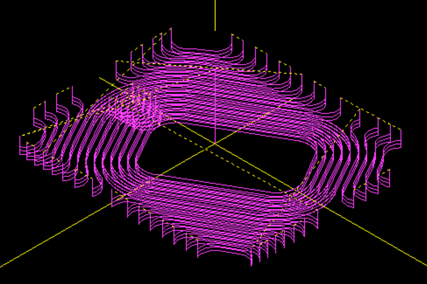
Analyzing each step of the workflow gave me an overview of the project. In the workflow, users interacted with the human-machine interface (HMI) on the controller to set the processing parameter. The controller then generated tool paths and converted them to machine instruction files. Finally, the users started machining and got the desired piece.

To collaborate with the product engineer, I provided an algorithm for generating tool paths. The next step was to figure out the proper input and the output requirements.

Analyze Input Parameters
Users inputted the parameters to describe the shape and the processing parameters:
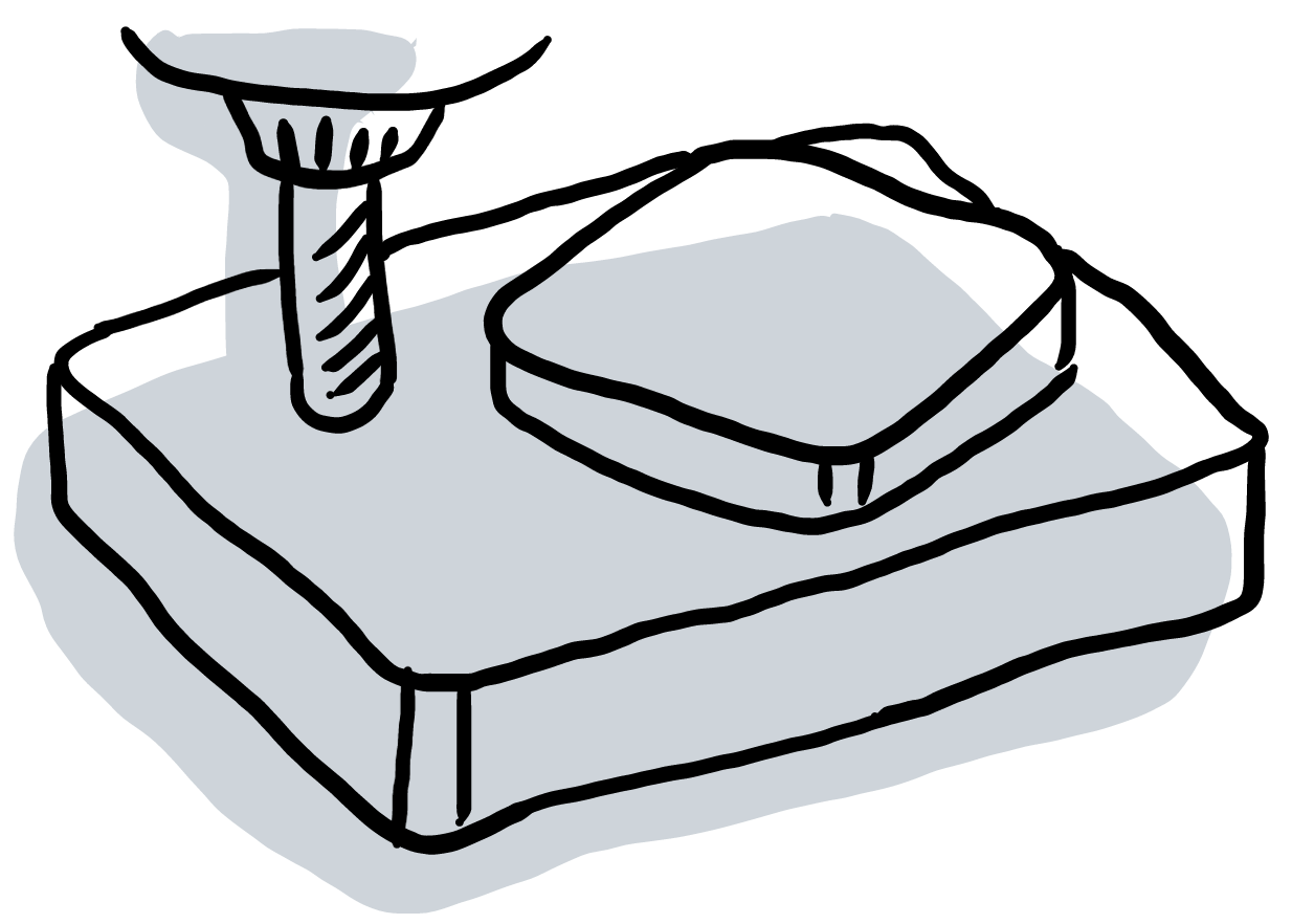
- Raw material descriptions: type (e.g., rectangle, circle), position, etc.
- Island shape description parameters: type (e.g., rectangle, circle, polygon), width, length, diameter, corner radius, etc.
- Tool path parameters: cutting direction (i.e., clockwise/counter-clockwise), axial depth per cut, axial/radial thickness, etc.


Analyze Output Requirements
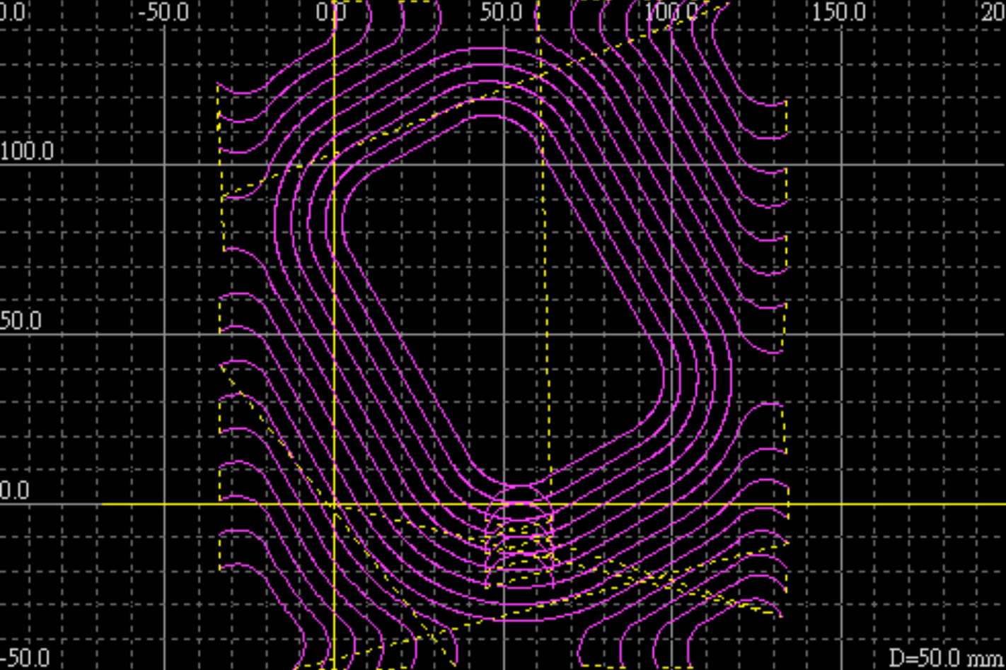
Examining the customer desired tool paths, I summarized the following rules:
- The tool paths had two types: closed loop and open loop.
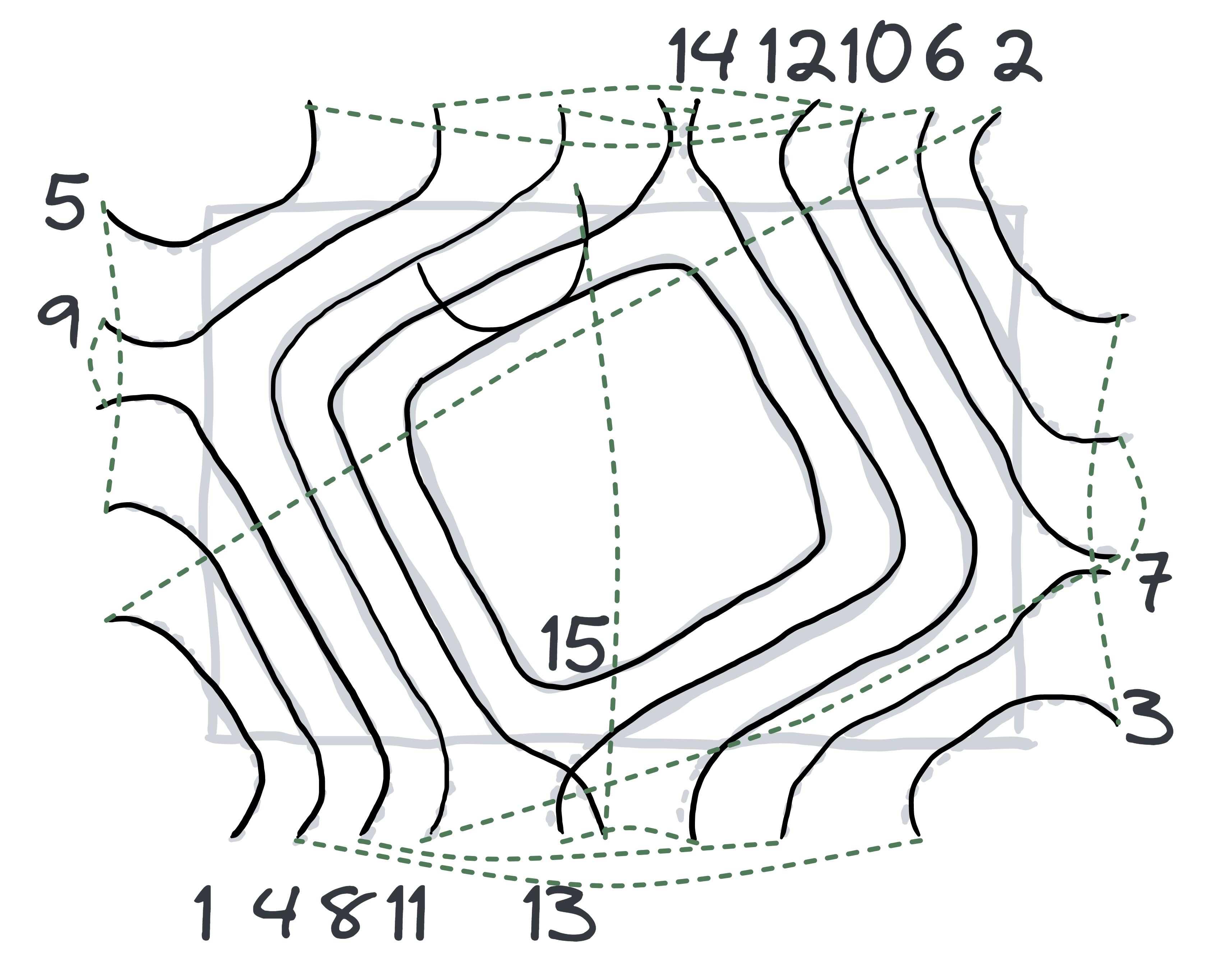
- The sequence of tool paths should be optimized for efficiency. Comparing the two planning methods: “from outside to inside” and “the same corner first,” processing the same corner first could shorten the total travel distance and increase productivity.
- Other parameters should set default values, e.g., the processing order of corners, retract height, etc.
Same Corner First
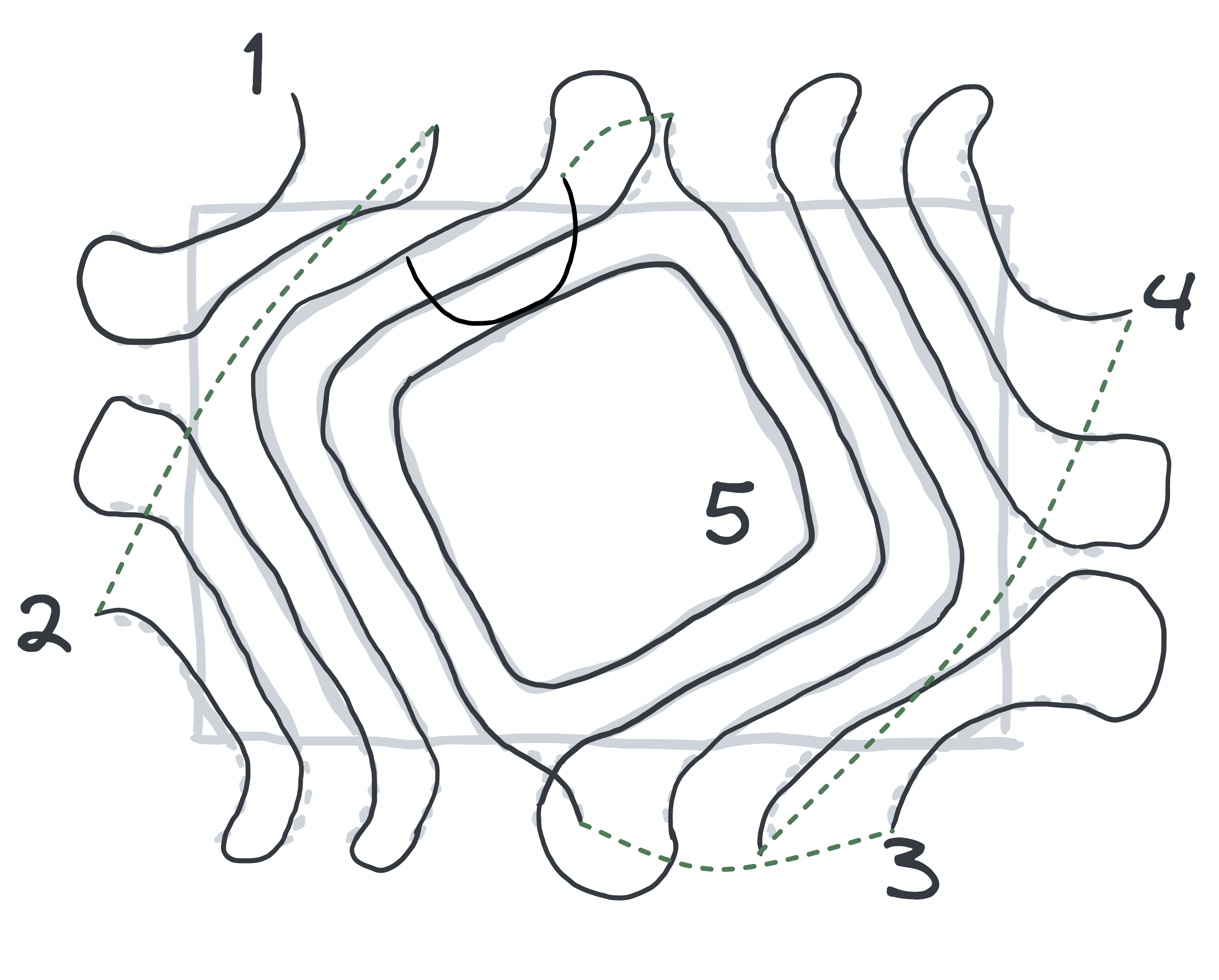
From outside to inside
Step 2: Define Interface
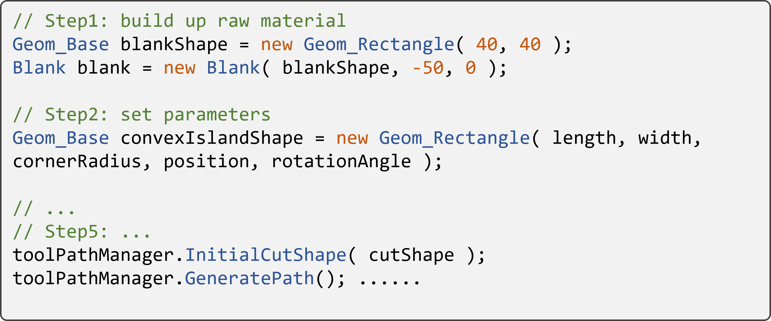
Before developing the algorithms, I designed the programming interface and provided the sample code for the product engineer.
- It was helpful to collaborate. Since the product engineer knew what the algorithm interfaces were, he could design and implement the user interface simultaneously.
- I could write the test codes in advance. The test codes helped me evaluate my work at the end of the project.

Step 3: Develop algorithms
I broke down the algorithm into smaller parts and found solutions for each piece. It could be separated into three parts: geometry offset, geometry trimming, and sorting the segment. Using a similar process, I defined each part's inputs and outputs. Then, I researched how to solve each part individually. For example, geometry offset was a laborious problem to be solved generally. Fortunately, I found an open-source solution and integrated it into our product since I did not want to reinvent the wheel. Using established stable libraries accelerated the development process. Moreover, I devised a method to sort the path segments in the same corner first strategy. In the end, I assembled each part and completed the task.
Geometry Offset

Geometry Trimming

Sorting Path Segments

Step 4: Evaluate Outcome
Since I designed the test cases in advance, I could use them to examine the outcome at early stages. Later, the co-worker further integrated my library into his code and delivered it to customers.
Reflection
In addition to a comprehensive solution, a focused and simplified one could also bring high satisfaction to customers. Since it was customized for the client, the project eliminated unused functions, which meant reduced distractions for the client. The client would experience fewer hurdles in completing the task. Therefore, the customer felt satisfied with the limited interactions to process the workpiece.
Defining a clear software interface benefited the collaboration with other developers. Providing sample code was also helpful for others to use. My colleague said the sample code helped him to integrate his human interface and my part smoothly. Also, since I had written thorough testing cases, he was confident to evaluate the final result.