
Brief

A laser marking system uses a focused laser beam to engrave a permanent mark on object surfaces. Laser marking is efficient, low in pollution, and applicable to various materials. Since laser marking can make high-precision figures, it is popular in both industrial production and commercial products, such as industrial components, packaging, keyboard, home decor gifts, etc.
The project’s goal was to offer a comprehensive laser marking solution for customers. The customers could buy the laser marking system as a complete package. The system included a laser source, a galvo scanner (an optical mirror module to control the direction of the laser beam), a controller, and application software. My responsibility was to develop the application software integrated into the system.

My Role
Product Engineer
- Interface Design
- Algorithms Development
- Software Maintenance
Skill
- C#
- G-code
- PLC
Timeline
2016/5 - 2019/5, 3 years
Team
Syntec Technology Co., Ltd.- Chin-Jen Cheng
- Ning-Hsiang Yu
- Hsing-Yi Ke
- Chen-Tang Fan
- Tzu-Chuan Yang
Introduction
Laser marking software allows users to design patterns, set processing parameters, and run execution files.
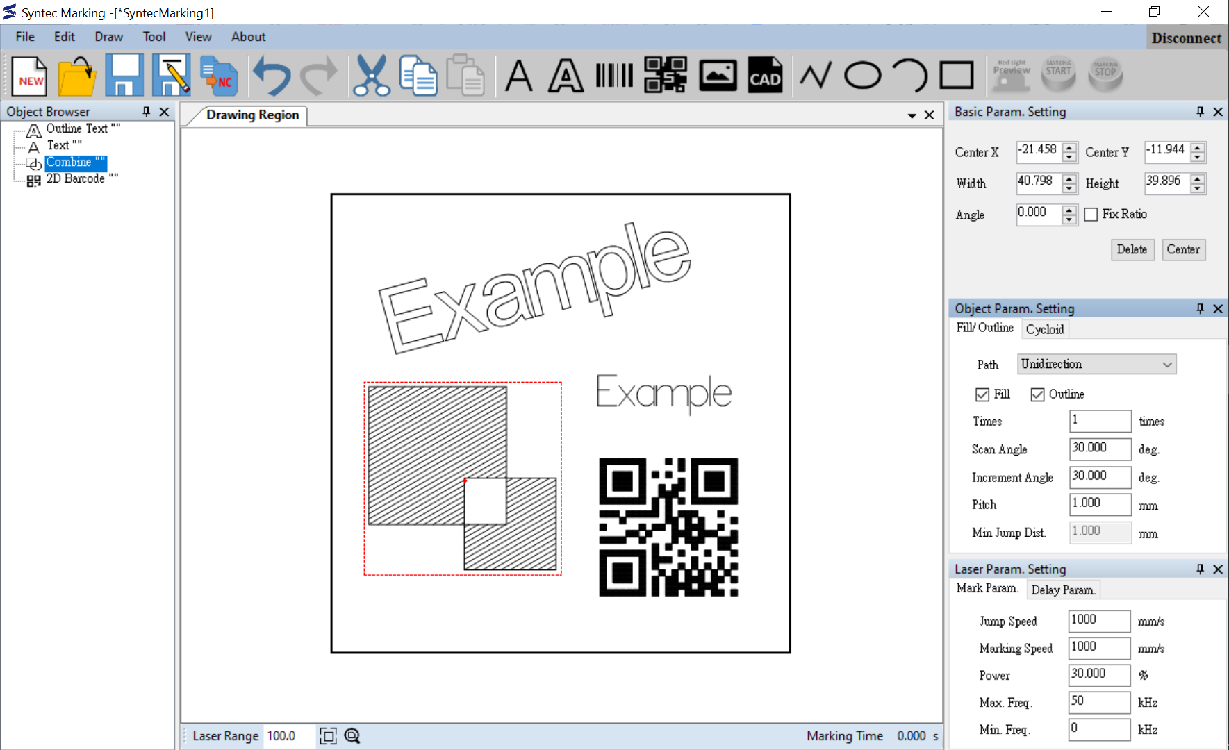
Key Feature 1: Drawing
Importing Files
Import DXF files and pictures.


Drawing Geometry
Draw rectangles, ellipses, polylines, etc.


Creating Text
Create single-line fonts and outlined fonts. Single-line fonts are for quick processing.


Generating Barcodes
Generate 1D barcodes and 2D barcodes, e.g., QR code, Data Matrix, etc.


Programmatic Number Sequencing
Users can customize rules for serial numbers and dates. The numbers increase for each execution.


Key Feature 2: Editing
Filling
Fill in the selected shape. The filling lines can be set to have a specified scanning angle, an incremental angle, repeated times, etc.

Cycloid Line
Turn lines into cycloid lines. It can have a widening effect on the pattern.

Curved Text
Bend text around the curve.

Combined Geometry
Combine multiple shapes.

Key Feature 3: Execution
Setting Laser Source Type and Processing Parameters
Support multiple laser source types and processing parameters, such as laser power, frequency, etc.
Red Light Preview
Use a red laser beam to project a preview image of the markings.

Execution
- Stand-along Scenario: Connect the laser marking system to the controller and execute.
- Industrial Scenario: Store the execution files on the controller and trigger the system autonomously. When integrating the marking system into production lines, the laser marking system can be triggered by other sensors, such as when the camera captures the object.
Case Study: Large Area Synchronous Laser Marking
Problem Statement
The laser marking workspace was limited by its optical mirror system. However, clients wanted to make a larger pattern, such as patterns on door boards. The solution for enlarging the workspace was to embed the laser marking system on a 3-axis platform. The platform was designed to steer the laser marking system.

Goal
The galvo scanner module limited the laser marking workspace to 100 mm * 100 mm. The goal was to enlarge the workspace.
Method
Investigate potential approaches:
Approach 1: Positioning Marking
- Divide the pattern into multiple 100 mm * 100 mm regions.
- Move the laser marking module to each region to engrave the pattern.
- Process each region individually until all regions were processed.


→ Because of the lens distortion, the neighboring patterns' margins would have gaps.
Approach 2: Synchronous Laser Marking
- Plan the platform and laser beam paths coordinately.
- Synchronize the platform motion and laser marking commands.

→ Since the patterns were marked continuously, they would not have neighboring gaps.
The next challenges were generating tool paths for both the 3-axis platform and the laser marking system and allowing them to coordinate smoothly.
In the beginning, I tried to visualize the paths. I drew the laser marking paths and expected platform paths, and an idea came to mind. Since the platform was very slow due to its inertia, I wanted it to travel a path simplified from the laser marking path. This way, the platform was responsible for taking the laser marking system to an approximate location, and the laser marking system could make more granular movements. To implement this idea, I further researched several polyline simplification algorithms and examined them with different criteria. For instance, the algorithms could easily control the deviation between the original lines and the simplified lines, so the laser marking path could stay in the workspace of the laser marking module while the 3-axis platform was moving. Later, to coordinate both paths, the velocities should be allocated to each segment appropriately.
Lastly, I developed simulation software to examine the result in order to shorten the development process (evaluating every modification on machines took a lot of time.) Ultimately, I tested the execution files on the machine and verified that they passed the designed test cases.
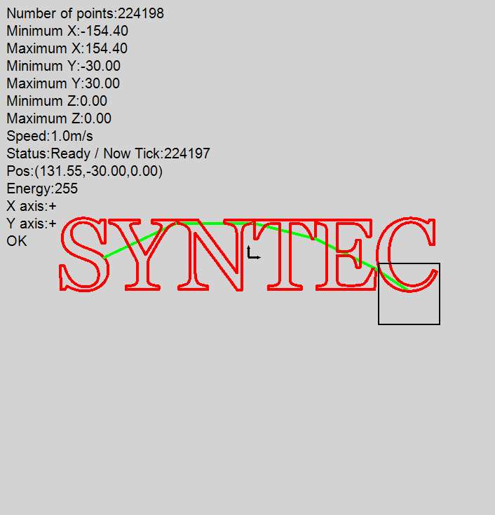
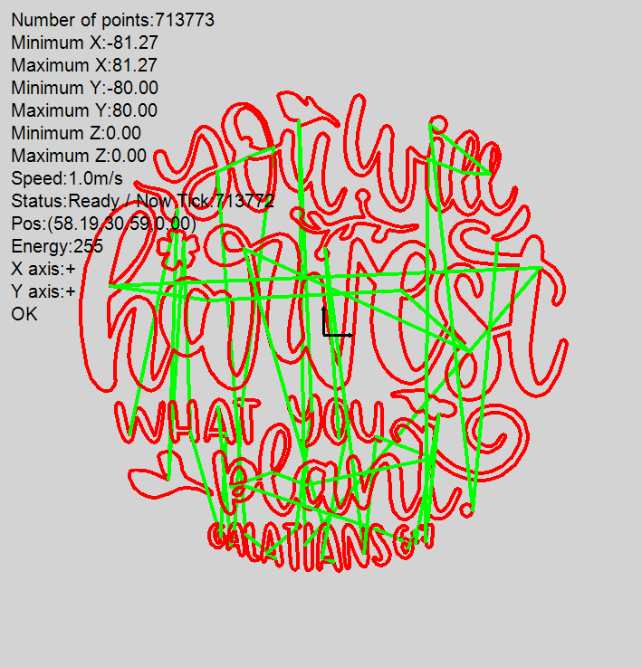
Simulation on the examination software. (The tool path of the platform is in green; The tool path of the laser beam is in red.)
Result
I succeeded in completing the algorithm and completed the evaluation on the machine. This feature attracted new customers for the company.
Reflection
- I developed several user interface features during the whole development process, such as zoom in/out, select objects, object browsers, etc. In the initial stage, I defined the specification by my idea. But occasionally, I got feedback that users felt they could not complete their tasks easily and were unsatisfying. After a while, whenever I had to develop user interfaces, I would draw wireframes or build interactive prototypes for users. Then, I could get feedback at the earlier stage of development. It helped me design practical interfaces efficiently.
- In the Large Area Synchronous Laser Marking project, planning the tool paths required knowledge of motion planning. At the beginning of the project, I found I needed more resources and asked for help. The research department trained our team about motion planning. With a common knowledge base, it was really helpful to streamline the process of later collaboration.
- Finding early adopters was critical to product development. Since the laser marking market was highly competitive, the early adopters assisted us in knowing which features were preferable to new clients. They played an important role in the decision-making of the product planning strategy. Our team built critical features based on their opinions to draw potential future customers.